Projects
UVic Formula Racing Team Projects
My first PCB design! This board was designed in Altium and was used on the UVFR EV 2026 as a dashboard with indicator lights for the IMD (Insulation Monitoring Device) and BMS (Battery Management System).
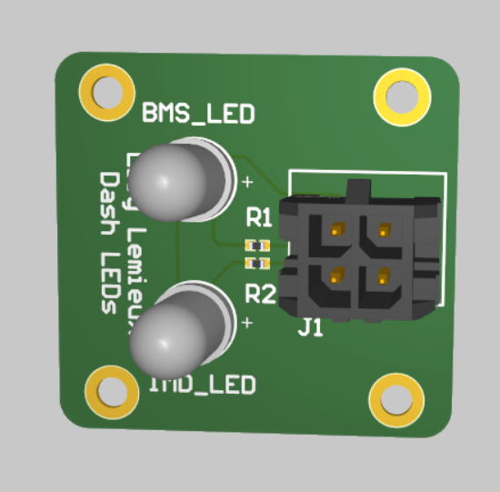
3D View of Dashboard PCB
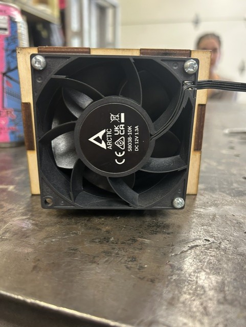
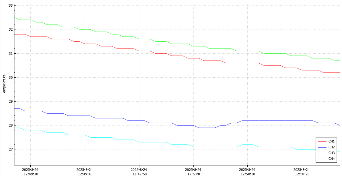
I conducted a series of airflow and cooling experiments with mock battery segments to gather data for the development of the Temperature Monitoring System (TMS) of the accumulator, which is basically the car's battery. I used thermocouples and their accompanying software, a DC fan, and a power supply to get some data for the first round of experiments.
To make the experiments more dynamic, I implemented fan speed control with Arduino, which gave us some insight into which fans were the most efficient. Additionally, I created a user manual including the code and the breadboard layout so that future members are able to recreate the same setup.
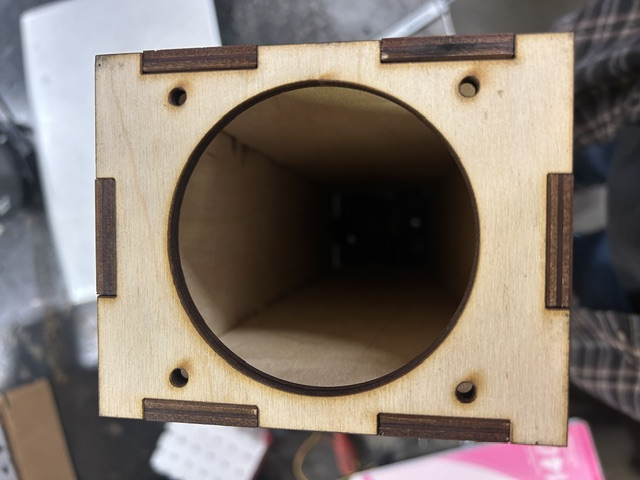
In order to test different fans, we required a specific mount for each. Using SolidWorks and basic measurement skills, I designed fan mounts for a variety of fans, enabling us to examine the data gained from each.
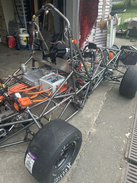
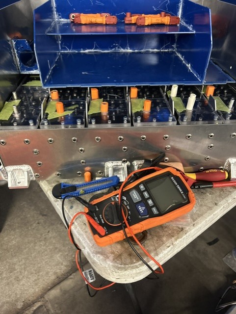
This spring I helped with the assembly of the EV! With my HV Trained certificate I was able to take part in the assembly of the accumulator including the testing of the battery segments to stripping and crimping HV wires!
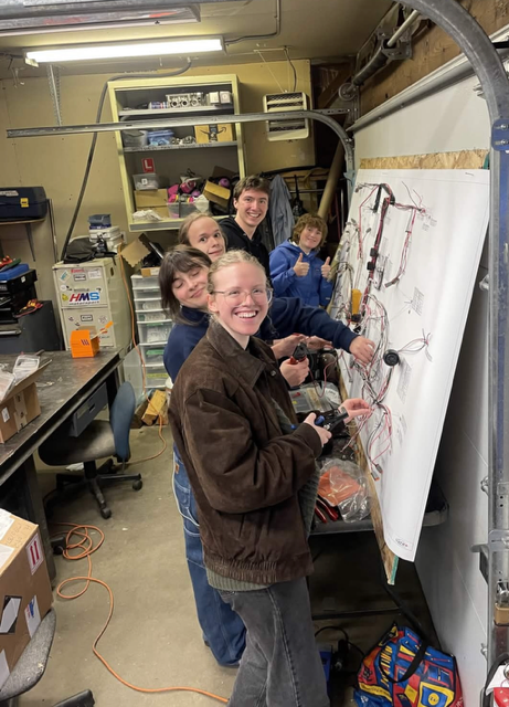
I worked on the wiring harness for the EV using RapidHarness to arrange connectors and organize wires while also gaining experience measuring lengths based on the chassis design in SolidWorks!
I also assisted with the assembly of the wiring harness, which was a very fun activity shared with the other members of the Electronics Subsystem.
The team ran into difficulty with the TMS at competition, so over the summer we started re-designing the system.
I worked on the Satellite Board which was mainly responsible for dealing with thermistor I/O.
This included analysis of the original system and the fixing of certain parts that were incorrect. The final board shown below adheres to FSAE competition rules and should work better with the new system (we have yet to order the board).
After finishing my edits to the Satellite Board, I did my first formal design review which included going over some features of the Main Board my teammate was working on. The experience of presenting the entire system gave me another chance to go over the circuitry and test my technical communication skills.
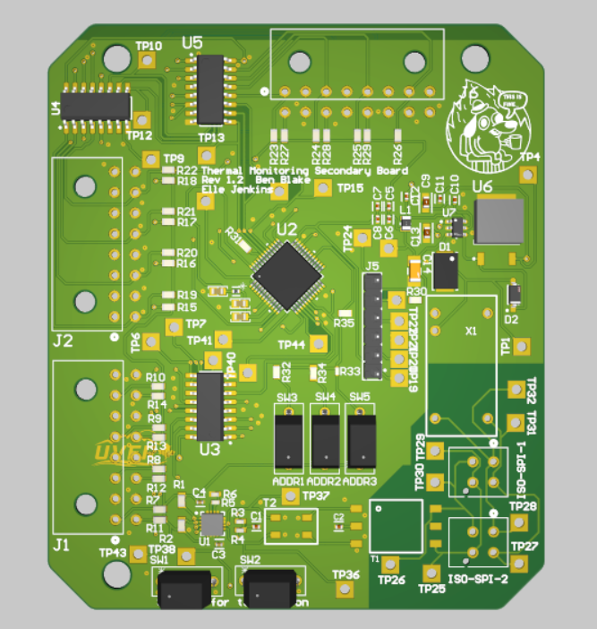
3D View of TMS Satellite Board
UVic Satellite Design Team Projects
During my work with the ground station, I helped with the purchase order for components needed to assemble an IC-9700 ground station. This process involved reading datasheets, researching component requirements, and determining what was necessary for the IC-9700 to function within the current focus of the club.
The OBC PCB upgrades involved updating the Altium schematics and accompanying layout for the second revision of this board, and updating a general template for future revisions.
Course Projects
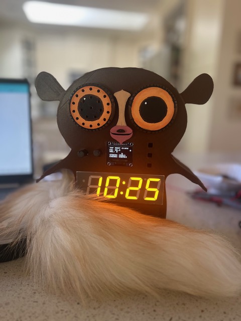
In ECE 299, Introduction to Electrical and Computer Engineering Design, my partner and I designed a Madagascar-themed Alarm Clock Radio with the following features:
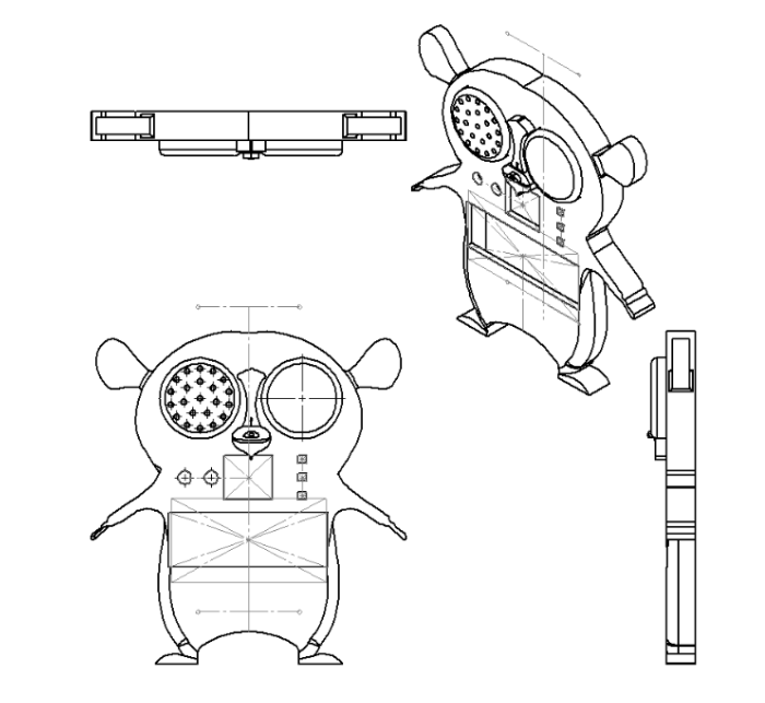
- A Mort-shaped enclosure designed in SolidWorks and 3D printed in the ECSS Makerspace
- Encoders and a User-Interface for both in-person and virtual controls
- An LCD display showing the system status and a 7-segment display capable of displaying the current time and alarm setting
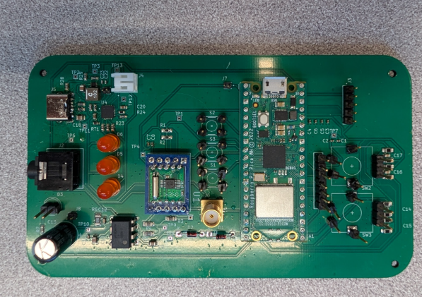
- A PCB designed in KiCad hosting the system circuitry including a Raspberry Pi Pico W development board
In ENGR 121, Design II, my team and I built a model Building Management System to pitch to UVic Facilities as a more sustainable way to manage HVAC and lighting across campus (hypothetical scenario).
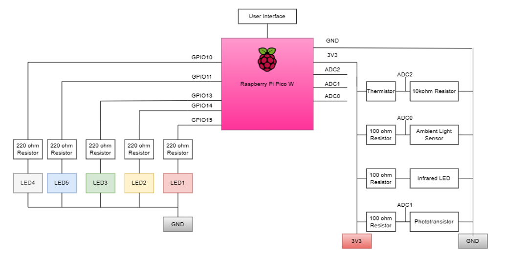
Our system was capable of reading the current ambient temperature, lighting, and occupancy in a given space. Systems remained off until the space was occupied, then the heating, air-conditioning and lighting systems were turned on or off depending on either the natural state of the space or a command from the User-Interface.
Whether a feature was on or off was shown on LEDs.
Our system was complete with a UI which connected to the Raspberry Pi Pico W wifi, making it possible for the user to see the HVAC, lighting, and occupancy status of a space and override the latter in real time.
The block diagram below shows the general layout.
Block Diagram of BMS